Product Description
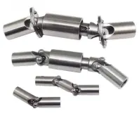
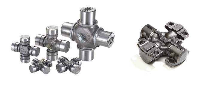
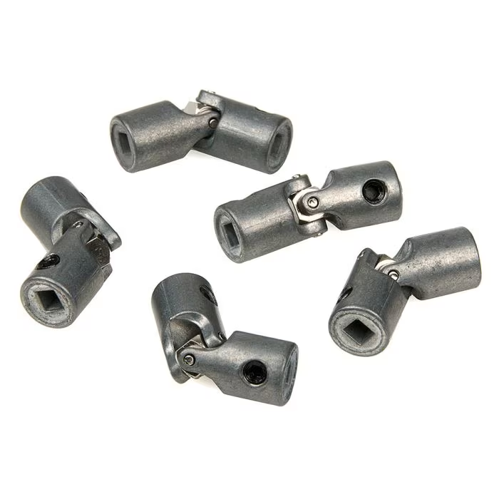
HangZhou Xihu (West Lake) Dis. Brand Cardan Shaft Spare Parts Universal Joint
Brief Introduction
Processing flow
Quality Control
Packaging & Delivery
Packaging details:Standard plywood case
Delivery detail: 3-15 working days,depend on the actual produce condition
FAQ
Q1: What is the location of your company?
A1: Our company is located in the HangZhou City ,ZheJiang ,China.Welcome to visit our factory at anytime!
Q2: How does your factory do regarding quality control?
A2: Our standard QC system to control quality.
Q3: What is your delivery time?
A3: Usually within 20 days after the receipt of payment.Delivery time must depend on the actual produce condition.
Q4: What are your strengths?
A4: 1.We are the manufacturer,having competitive advantage in price.
2.A large part of money is put into advancing CNC equipments and product
R&D department annual,the performance of cardan shaft can be guaranteed.
3.About quality issues or follow-up after-sales service,we report directly to the boss.
Specification
There is no uniform standard for the specifications of cross assemblies. Please contact us directly for confirmation.
/* January 22, 2571 19:08:37 */!function(){function s(e,r){var a,o={};try{e&&e.split(“,”).forEach(function(e,t){e&&(a=e.match(/(.*?):(.*)$/))&&1
| Condition: | New |
|---|---|
| Color: | Silver |
| Certification: | ISO, BV |
| Structure: | Cross |
| Material: | Forging |
| Type: | Cross |
| Customization: |
Available
| Customized Request |
|---|

How do you calculate the torque capacity of a universal joint?
Calculating the torque capacity of a universal joint involves considering various factors such as the joint’s design, material properties, and operating conditions. Here’s a detailed explanation:
The torque capacity of a universal joint is determined by several key parameters:
- Maximum Allowable Angle: The maximum allowable angle, often referred to as the “operating angle,” is the maximum angle at which the universal joint can operate without compromising its performance and integrity. It is typically specified by the manufacturer and depends on the joint’s design and construction.
- Design Factor: The design factor accounts for safety margins and variations in load conditions. It is a dimensionless factor typically ranging from 1.5 to 2.0, and it is multiplied by the calculated torque to ensure the joint can handle occasional peak loads or unexpected variations.
- Material Properties: The material properties of the universal joint’s components, such as the yokes, cross, and bearings, play a crucial role in determining its torque capacity. Factors such as the yield strength, ultimate tensile strength, and fatigue strength of the materials are considered in the calculations.
- Equivalent Torque: The equivalent torque is the torque value that represents the combined effect of the applied torque and the misalignment angle. It is calculated by multiplying the applied torque by a factor that accounts for the misalignment angle and the joint’s design characteristics. This factor is often provided in manufacturer specifications or can be determined through empirical testing.
- Torque Calculation: To calculate the torque capacity of a universal joint, the following formula can be used:
Torque Capacity = (Equivalent Torque × Design Factor) / Safety Factor
The safety factor is an additional multiplier applied to ensure a conservative and reliable design. The value of the safety factor depends on the specific application and industry standards but is typically in the range of 1.5 to 2.0.
It is important to note that calculating the torque capacity of a universal joint involves complex engineering considerations, and it is recommended to consult manufacturer specifications, guidelines, or engineering experts with experience in universal joint design for accurate and reliable calculations.
In summary, the torque capacity of a universal joint is calculated by considering the maximum allowable angle, applying a design factor, accounting for material properties, determining the equivalent torque, and applying a safety factor. Proper torque capacity calculations ensure that the universal joint can reliably handle the expected loads and misalignments in its intended application.

What are the signs of a failing universal joint and how do you diagnose it?
Diagnosing a failing universal joint involves identifying specific signs and symptoms that indicate potential problems. Here’s a detailed explanation:
A failing universal joint can exhibit several signs that indicate a need for inspection, repair, or replacement. Some common signs of a failing universal joint include:
- Clunking or Knocking Noise: One of the most noticeable signs is a clunking or knocking noise coming from the universal joint area. This noise is often more pronounced during acceleration, deceleration, or when changing gears. The noise may indicate excessive play or wear in the joint’s components.
- Vibration: A failing universal joint can cause vibrations that are felt throughout the vehicle. These vibrations may be more noticeable at higher speeds or under load conditions. The vibrations can be a result of imbalanced driveshafts or misaligned yokes due to worn or damaged universal joint bearings.
- Difficulty in Power Transfer: As a universal joint deteriorates, power transfer from the transmission to the driven wheels may become less efficient. This can lead to a decrease in acceleration, reduced towing capacity, or difficulty in maintaining consistent speed. Loss of power transfer efficiency can occur due to worn or seized universal joint components.
- Visible Wear or Damage: A visual inspection of the universal joint can reveal signs of wear or damage. Look for excessive play or movement in the joint, rust or corrosion on the components, cracked or broken yokes, or worn-out bearings. Any visible signs of damage indicate a potential issue with the universal joint.
- Grease Leakage: Universal joints are typically lubricated with grease to reduce friction and wear. If you notice grease leakage around the joint or on the surrounding components, it may indicate a failing seal or a damaged bearing, which can lead to joint failure.
To diagnose a failing universal joint, the following steps can be taken:
- Perform a visual inspection: Inspect the universal joint and surrounding components for any visible signs of wear, damage, or leakage. Pay attention to the condition of the yokes, bearings, seals, and grease fittings.
- Check for excessive play: While the vehicle is on a level surface and the parking brake is engaged, attempt to move the driveshaft back and forth. Excessive play or movement in the universal joint indicates wear or looseness.
- Listen for abnormal noises: During a test drive, listen for any clunking, knocking, or unusual noises coming from the universal joint area. Pay attention to noise changes during acceleration, deceleration, and gear changes.
- Monitor vibrations: Note any vibrations felt through the vehicle, especially at higher speeds or under load conditions. Excessive vibrations can indicate problems with the universal joint or driveshaft.
- Seek professional inspection: If you suspect a failing universal joint but are uncertain about the diagnosis, it’s recommended to consult a professional mechanic or technician with experience in drivetrain systems. They can perform a comprehensive inspection, including measurements and specialized tests, to accurately diagnose the condition of the universal joint.
It’s important to address any signs of a failing universal joint promptly to avoid further damage, drivability issues, or potential safety hazards. Regular maintenance, including periodic inspection and lubrication, can help prevent premature universal joint failure.
In summary, signs of a failing universal joint include clunking or knocking noises, vibrations, difficulty in power transfer, visible wear or damage, and grease leakage. Diagnosing a failing universal joint involves visual inspection, checking for excessive play, listening for abnormal noises, monitoring vibrations, and seeking professional inspection when necessary.

What is a universal joint and how does it work?
A universal joint, also known as a U-joint, is a mechanical coupling that allows for the transmission of rotary motion between two shafts that are not in line with each other. It is commonly used in applications where shafts need to transmit motion at angles or around obstacles. The universal joint consists of a cross-shaped or H-shaped yoke with bearings at the ends of each arm. Let’s explore how it works:
A universal joint typically comprises four main components:
- Input Shaft: The input shaft is the shaft that provides the initial rotary motion.
- Output Shaft: The output shaft is the shaft that receives the rotary motion from the input shaft.
- Yoke: The yoke is a cross-shaped or H-shaped component that connects the input and output shafts. It consists of two arms perpendicular to each other.
- Bearings: Bearings are located at the ends of each arm of the yoke. These bearings allow for smooth rotation and reduce friction between the yoke and the shafts.
When the input shaft rotates, it causes the yoke to rotate along with it. Due to the perpendicular arrangement of the arms, the output shaft connected to the other arm of the yoke experiences rotary motion at an angle to the input shaft.
The universal joint works by accommodating the misalignment between the input and output shafts. As the input shaft rotates, the yoke allows the output shaft to rotate freely and continuously despite any angular displacement or misalignment between the two shafts. This flexibility of the universal joint enables torque to be transmitted smoothly between the shafts while compensating for their misalignment.
During operation, the bearings at the ends of the yoke arms allow for the rotation of the yoke and the connected shafts. The bearings are often enclosed within a housing or cross-shaped cap to provide protection and retain lubrication. The design of the bearings allows for a range of motion and flexibility, allowing the yoke to move and adjust as the shafts rotate at different angles.
The universal joint is commonly used in various applications, including automotive drivelines, industrial machinery, and power transmission systems. It allows for the transmission of rotary motion at different angles and helps compensate for misalignment, eliminating the need for perfectly aligned shafts.
It is important to note that universal joints have certain limitations. They introduce a small amount of backlash or play, which can affect precision and accuracy in some applications. Furthermore, at extreme angles, the operating angles of the universal joint may become limited, potentially causing increased wear and reducing its lifespan.
Overall, the universal joint is a versatile mechanical coupling that enables the transmission of rotary motion between misaligned shafts. Its ability to accommodate angular displacement and misalignment makes it a valuable component in numerous mechanical systems.


editor by CX 2024-05-02